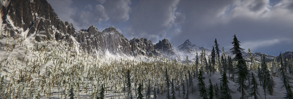
Giving a breakdown on generating procedural terrains in Unity 3D and how a simple droplet-erosion algorithm can be written in C#.
Introduction
Hi, my name is George Weiner, I'm from Vienna, Austria. I am currently studying a Game-Programming program at SAE-Vienna.
I've always been fascinated with generating terrains and heightmaps. It started when I was 13 and I downloaded the CryEngine 3 SDK.
I remember finding this tutorial series by Amir Abdaoui: https://youtu.be/p0o3bqoM0Qg and seeing how the terrain was generated in software called World Machine.
However, this project was different in that all of the creation of the terrain had to be done procedurally in-engine. This proved to be an interesting challenge with many iterations to get the final result.
Project Goals
Procedural Terrain is one of the research topics of the University Course and the goal of this project was to create terrain entirely in-engine as an exercise in procedural content generation. The goal was the create visually appealing and natural-looking terrain.
Reference
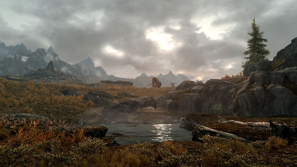
Having references is always important when you want to create something visual. It will give you a guideline and will help you to find new inspiration when choosing materials and parameters for the terrain. I chose The Elder Scrolls: Skyrim as one of my inspirations and ended up using it as a main reference.
Setting up the project
I set up my project to use the HDRP, as I was targeting high-end hardware with this project. Using HDRP seemed like the correct choice, as it gives me access to many desirable rendering techniques. By leveraging these features, you can create a visually convincing environment that can greatly enhance the overall quality of your project.
For this project, I used Unity 2021.3.4f1.
Starting with the basics
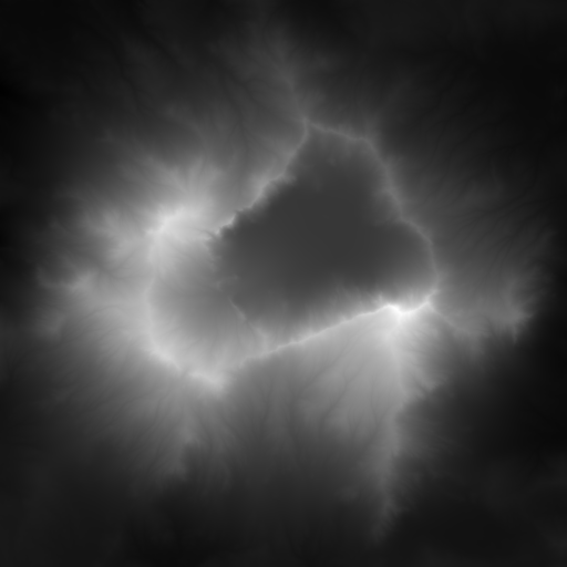
In most implementations, terrain data is stored as a 2D raster image called a heightmap. This heightmap is essentially a greyscale picture where white pixels represent the number 1 and black pixels represent the number 0. When a heightmap is projected onto a terrain, each pixel on the image corresponds to a location on the terrain mesh, which is then adjusted based on the global up-vector.
Creating basic shapes
The initial step in procedurally creating terrains typically involves generating a heightmap using some form of noise. In Unity 3D, one of the easiest ways to achieve this is by utilizing Perlin Noise with octaves, also known as fractional Brownian motion. This can be implemented quite easily:
private void InitializeSeed()
{
    if (!generateSeed)
        Random.InitState(seed);

    offsetX = Random.Range(-10000, 10000);
    offsetZ = Random.Range(-10000, 10000);
}


public float[,] GenerateNoiseMap(float offsetX, float offsetZ)
{
    float scale = perlinScale;
    var noiseMap = new float[terrainSize, terrainSize];

    var offsets = new Vector2[numOctaves];
    for (var i = 0; i < numOctaves; i++)
    {
        offsets[i] = new Vector2 (offsetX, offsetZ);
    }

    for (var zIndex = 0; zIndex < terrainSize; zIndex++)
    {
        for (var xIndex = 0; xIndex < terrainSize; xIndex++)
        {
            scale = perlinScale;
            var weight = 1f;

            //Apply octaves / fractals of noise, aka fractional Browning motion (fBm) or
            fractional Browning surface
            for (var octave = 0; octave < numOctaves; octave++)
            {
                Vector2 position = offsets[octave] + new Vector2(zIndex / (float)
                terrainSize, xIndex / (float) terrainSize) * scale;
                noiseMap[zIndex, xIndex] += Mathf.PerlinNoise(position.y, position.x) *
                weight * heightNormalizationFactor;

                weight *= persistence;
                scale *= lacunarity;
            }
        }
    }

    return noiseMap;
}
We start by creating two for-loops one for the x-axis and one for the y-axis. Looping over each grid cell we add Perlin Noise in continually smaller scales and smaller weights on top of each other.
This can be visualized like this:

In the last picture, you can already see something that vaguely resembles a terrain. With this noisemap established we apply it to the Unity Terrain System. I created a static Terrain Setter class that allows me to set the terrain from anywhere within my program.
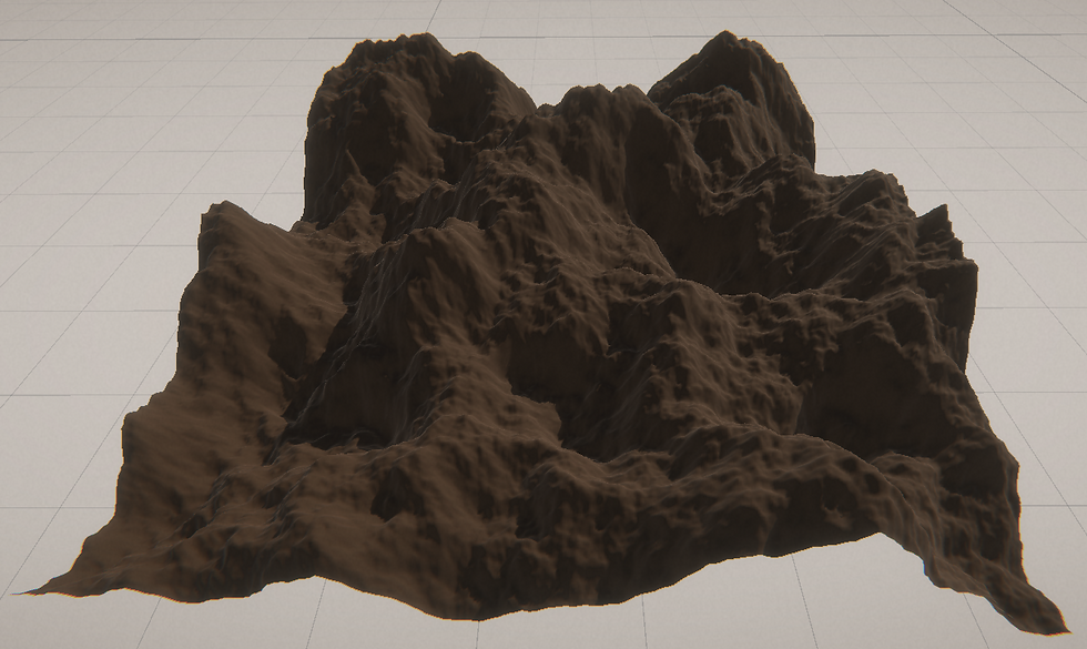
This example is a 512x512 terrain with 8 octaves of Perlin noise. As you can see it already somewhat resembles a landscape, but we can improve upon this quite easily. Let's evaluate each pixel in the heightmap via a curve function. I used Unity's Animation Curve for this.
var heightMap = new float[terrainSize, terrainSize];
//Loop over each pixel and evaluate its height via a curve
for (var z = 0; z < noiseMap.GetLength(0); z++)
    for (var x = 0; x < noiseMap.GetLength(1); x++)
    {
        heightMap[z, x] = generationCurve.Evaluate(noiseMap[z, x]);
    }
These three terrains are all using the same seed when generating the Perlin Noise. Simply changing the curve over which to evaluate dramatically changes the appearance of the terrain and gives you a lot of control when trying to match references.
Eroding the Terrain
One technique that you may find helpful is the Particle-based Erosion Algorithm, which is described in detail in a Bachelor Thesis by Hans Beyer. You can access the thesis at this link: https://www.firespark.de/resources/downloads/implementation%20of%20a%20methode%20for%20hydraulic%20erosion.pdf
If you're interested in learning more about this algorithm, I highly recommend checking out the paper. It provides a comprehensive explanation of the method and can help you better understand how to apply it to your own terrain creation projects.
In short, the Particle-based Erosion Algorithm simulates the impact of water on the terrain by creating erosion marks from running water. This is achieved through a particle-based approach, where each particle is represented by its position, direction, speed, water amount, and sediment. The algorithm moves a droplet along the path of least resistance from its starting position to a local minimum, with the droplet's new direction being a blend between its old direction and the gradient of the height map at the current position. When the droplet moves down a slope, it takes some sediment from the terrain and subtracts height from the corresponding point on the height map. Conversely, when the droplet moves up a slope, it deposits sediment at the corresponding point and adds to the height. Through this process, the algorithm creates erosion marks that can significantly enhance the natural look and feel of the terrain.
Click to see the Hydraulic Erosion Algorithm
Let's apply this to our initial heightmap.
This already looks a lot more visually appealing and natural looking. We get some nice flow-lines along the steep slopes and valleys that get flatter and smoother, making the terrain look better and more suitable for gameplay purposes.
Creating a Terrain Shader
The next step lies in creating a simple terrain shader. Using a Triplanar shader is a good choice for terrains, as it prevents unwanted stretching on steep slopes. Let's create a new HDRP lit shader graph.
Start by recreating the following setup:
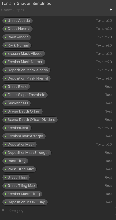

It calculates the slope of the terrain and determines at which height the grass should start blending with the rock texture. Based on the slope of the terrain, it calculates a weight value for the grass texture, which is used to blend the grass and rock textures. The final appearance of the surface is determined by combining the grass colour and rock colour based on the weight value.
To further enhance the visual quality of the terrain, it is advisable to sample the camera's depth buffer before replacing the gradient with textures. This is done to determine the appropriate tiling amount for the terrain, resulting in less noticeable tiling when viewed from a distance.
To sample the depth buffer, the following setup can be used:

We can then use the result of this to lerp between different texture tilings during the fragment-shader stage.
The next step is to create a couple of Triplanar nodes. In this example, I am going to keep it simple and only use two different texture tilings but feel free to use as many as you want.
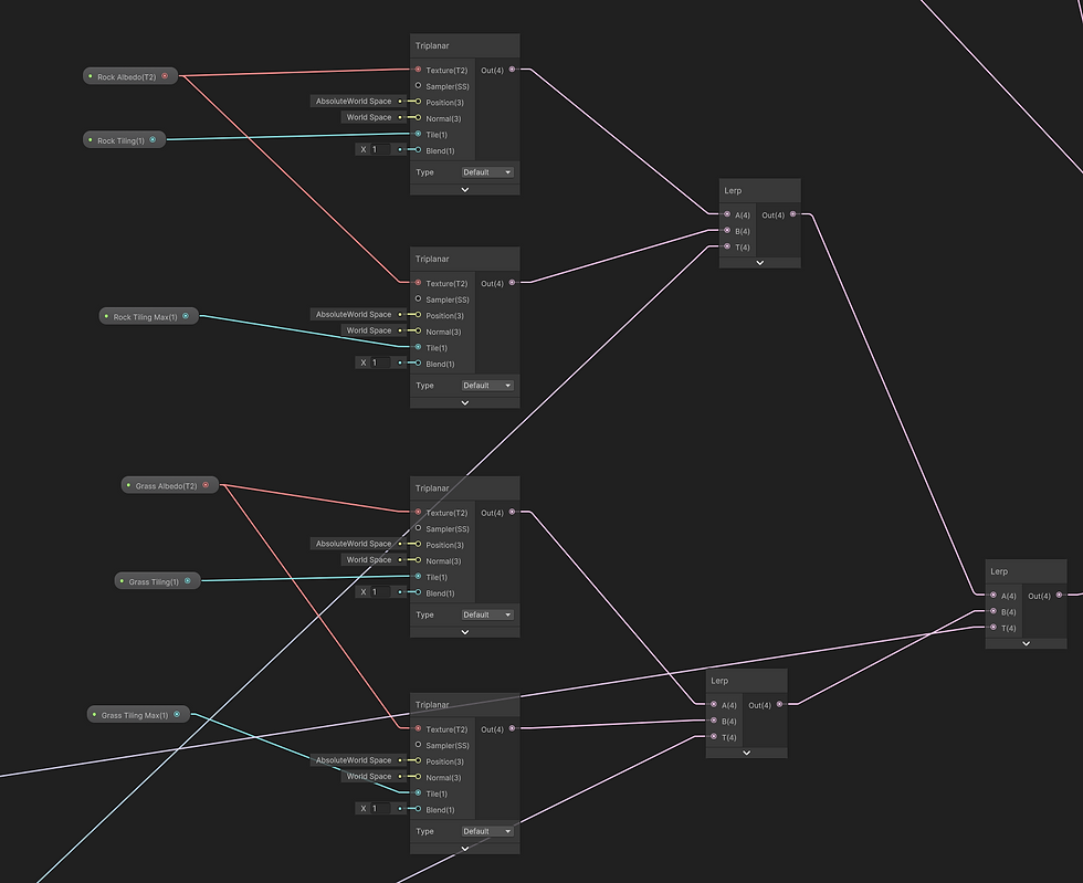
Here the alpha value of the first two lerps is the result of the depth buffer we did above. The second lerp takes the gradient we did in the beginning as alpha input.
We do the same thing for the normal maps: (I know it is hard to see, but I figured I'll include it anyways.)
Plugging the results into the base color and normal map input of the shader gives us the following result:
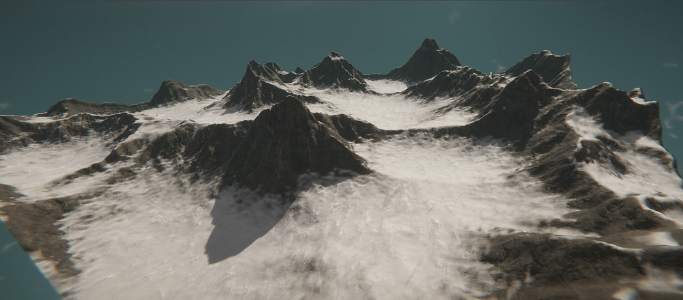
Now that is already pretty cool, but we can do even better!
One way to enhance your shader is by using the Erosion Code.
You may have noticed that the Erosion Code involves creating two separate two-dimensional float arrays: an Erosion Mask and a Deposition Mask. These masks can be used as textures in a shader to further improve the visual quality of the terrain.
To achieve this, you can create two texture parameters called 'Erosion Mask' and 'Deposition Mask', which can then be set via code. In the TerrainSetter.cs class, you can implement two methods to set these textures, allowing you to create even more detailed and immersive terrains that are better suited for your game's needs.
private static readonly int ErosionShaderMainTextureProperty = Shader.PropertyToID("_ErosionMask");
private static readonly int DepositionShaderMainTextureProperty = Shader.PropertyToID("_DepositionMask");

public static void ApplyMaterialMasks(UnityEngine.Terrain terrain, float[,] erosionMask, float[,] depositionMask)
{
    var erosionMaskTex = WriteArrayToTexture(erosionMask, depositionMask);
    var depositionMaskTex = WriteArrayToTexture(depositionMask, depositionMask);
    terrain.materialTemplate.SetTexture(ErosionShaderMainTextureProperty, erosionMaskTex);
    terrain.materialTemplate.SetTexture(DepositionShaderMainTextureProperty, depositionMaskTex);
}


private static Texture2D WriteArrayToTexture(float[,] erosionMask, float[,] depositionMask)
{
    Texture2D tex = new Texture2D(erosionMask.GetLength(0), erosionMask.GetLength(1));

    for (var x = 0; x < erosionMask.GetLength(0); x++)
    {
        for (var y = 0; y < erosionMask.GetLength(1); y++)
        {
            var colorErosion = erosionMask[x, y] * 20;
            var colorDeposition = depositionMask[x, y] * 255;
            tex.SetPixel(y, x, new Color(colorErosion, colorErosion, colorErosion));
        }
    }

    tex.Apply();
    return tex;
}
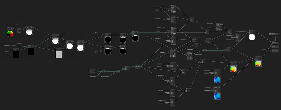
I applied these using more lerps to layer more textures on top of each other. To really get an overview of the shader I recommend cloning the project from GitHub and having a look at it yourself. It's a bit hard to show this off here with limited-size pictures.
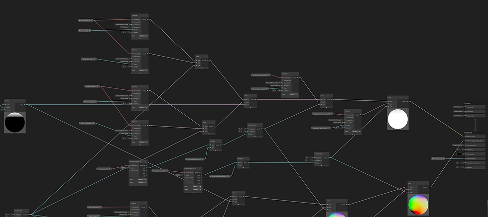
Here is a screenshot of the whole setup:
Shader Results:
Scattering Objects:
To keep this article concise, I won't delve into the object scatterer in great detail, but you can access all the project files and source code on my GitHub page. In this section, I use a noisemap to scatter objects and populate the scene. Specifically, I generate a single layer of Perlin noise with a large scale to create a mask for object placement. Then, I fire raycasts onto the terrain and record the point of impact. To facilitate this process, I utilize scriptable objects as data containers to store parameters for prefab placement (such as minimum and maximum height, slope, etc.). It's worth noting that every asset in the accompanying screenshots has been procedurally placed.
Final Result:
In conclusion, creating procedural terrains can be a fascinating and rewarding task. With Unity 3D, it's relatively easy to generate complex and visually stunning landscapes. The droplet-erosion algorithm we explored is just one of many methods for generating terrain in Unity, and there are plenty of other techniques and tools available to experiment with. By combining different algorithms, adjusting parameters, and utilizing references, you can create terrains that are unique and tailored to your specific needs.
For the future, I would like to look into Compute Shaders, making experimenting on high-resolution terrains more practical, as well as using more pre-generated masks for shaders and object scattering.
If you enjoyed this quick overview, please feel free to dig into the project files yourself or E-Mail me at gecovin@protonmail.com


Commentaires